|
|
| Background |
Serial interfaces have been in heavy use for more than 30 years. While there are many other options
for interfacing devices available now, it will probably be another 30 years before these interfaces
disappear.
In the beginning, even before computer screens existed, serial interfaces were used to connect
keyboards and teletypes to central processing units. Information typed on the keyboard could then
be printed on the "teletypes" which later became known as printers. The first computer screens
which also used serial interfaces, were commonly called "Glass Teletypes" because they emulated the
teletype printers without using paper.
Since then, serial interfaces have been used to connect almost every imaginable type of device including:-
- keyboards
- printers
- screens
- modems
- computers
- computer terminals
- barcode scanners
- customer displays
- cash drawers
And many other types of device.
Some of these devices only ever send data. For example barcode readers only ever send data.
Some devices only ever receive data, such as a computer screen, printer or customer display.
Other devices both send and receive data, such as modems, computers and terminals.
The fact that serial interfaces can work reliably to connect all of these types of devices
indicates how flexible this type of interface really is.
This flexibility however, has resulted in some of the most serious drawbacks to the serial interface.
This is because it has led to a great range of interpretations as to how the RS232 standard should be
applied, resulting in differences between manufacturers. While many of these differences no longer
a problem because certain conventions have been adopted that is not always the case.
The serial interface is clearly bi-directional, or in other words, capable of passing data in
both directions. But not every device actually sends data both ways. Often the manufacturer of
Customer Pole displays figure that this device will never send data, so why build in the
parts of the interface that send data? But the manufacturer of the computer that you are trying to
connect to this customer display has implemented communication both ways and the interface on the
computer end won't work until it receives signals from the device on other end that everything is OK...
Signals that the other device never provides because it knows it will never use them.
To make things worse, the technical documentation supplied by the equipment manufacturers is, often as not,
just plain wrong and misleading.
All this might sound very bad. The good news is that if you understand how serial interfacing actually
works then you can make any serial device connect to any other serial device without a great deal of
difficulty. And without having any of the technical documentation from the manufacturer.
To illustrate how to interface serial devices without any documentation, we are going to interface
this old receipt printer so that it works with SELLmatix Point of Sale running on a PC.
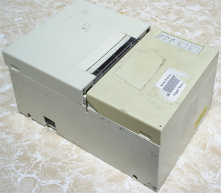
This old clunker was bought from a pile of junk for $5.00. The labels that normally show the
manufacturer and the model were missing so there was no way to identify the printer. After a
good cleaning with Ajax and various household cleaners however it came up looking quite respectable.
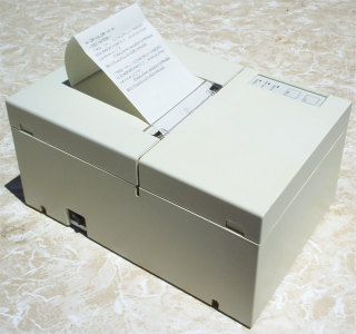
It even printed a self test OK. Self test can usually be run by holding down the Online, or Paper Feed
buttons on the printer while turning on the power. The device seemed to work OK, can we make it work with
the computer?
First, a few more details about serial interfaces and how they work.
Back to top | | |
|
Cable Types and Lengths |
The main reason for choosing a device with a serial interface these days, is the length of the cable that can be used.
Parallel ports are much faster for data transfer in a single direction which makes them very good for printers, but parallel cables don't
work much beyond 5 meters in length.
USB devices are good for bi-directional data transfer, but after 15 meters, you begin to need repeaters to boost the signal.
With serial ports, however, you can go far, far beyond these limitations. But the restriction is communication speed and the correct type cable must be used, and the cable
situated correctly.
The original RS-232 specification limited cable length to 15.25 meters at a data rate of 19,200 bits per second, or a cable length equal to a capacitance of 2500 pF. At the time, few UART chips (Universal Asynchronous Receiver Transmitter) that control the
Serial interface could operate at 19,200bps. Now, however, they can go well beyond.
Maximum cable length depends on a range of factors including the performance of the UART chips, the cable capacitance, inductance and screening. These are difficult to quantify, but the main factor is the communication speed. Generally speaking, doubling the data rate halves the recommended maximum length.
As a general rule of thumb, the following table shows what can reasonably be expected with good quality cable routed in such a manner as to minimise interference.
| Data Rate (bps) |
Maximum Length |
|
2,400 |
120m (400ft) |
|
4,800 |
60m (200ft) |
|
9,600 |
30m (100ft) |
|
19,200 |
15m (50ft) |
|
38,400 |
7.5m (25ft) |
|
57,600 |
5m (16ft) |
|
115,200 |
2.5m (8ft) |
In Point of Sale applications, the main consideration for serial cabling will be the physical location of the device. If you are installing a kitchen printer that is 60 meters away from the computer
driving the printer, there is not much you can do about it. And it does not really matter if it takes an additional 2 seconds to print the order in any case.
In an effort to tweak things and get the best performance, people are sometimes tempted to try things such as increasing the size of the cable to reduce voltage drop. With Serial interfaces however, this is not the problem
because the acceptable voltage ranges are very broad. Instead, the limiting factor is the capacitance of the cable, so that in fact, thinner serial cables work better over long distances than thick cables.
Serial cables are very vulnerable to interference. It is very important that the correct type of cable be used. The following picture shows the differences between correct serial interface cable on the left, and
Unshielded Twisted Pair (UTP) or CAT5 cable that is used for network (LAN) connections on the right.
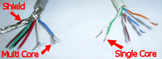
Notice that the serial cable has strands of wire woven around the inner insulated cores. This shielding is not used for any electrical connection, it is merely to reduce the effect of electromagnetic fields.
When making up a serial cable, this shielding is stripped back and cut off. If you see a serial cable where any electrical connection is made using this shielding, that tells you that the person that made the
cable did not know what they were doing!. This shielding does not exist on UTP CAT5 network cable.
Also notice that the inner wire cores on the serial cable are made up of multiple small strands of wire, while the CAT5 cable has a single core in each of the wires.
The CAT5 network cable is also referred to as UTP meaning "Unshielded Twisted Pair". Notice that it consists of 4 pairs that are each twisted together, for a total of 8 wires. Serial cables could have anywhere between 2 and 9 cores, since not all of the wires need to be present
in all serial cables.
The electrical properties of shielded serial cable and CAT5 network cable are quite different.
We continue to be amazed at how many contractors there are who should know better, but think that they can use CAT5 cable for serial connections because there are a similar number of cores. In certain cases, you might get away with this if you are lucky.
But if you are not so lucky, it can result in data loss, devices rebooting or locking up for no apparent reason, and even physical damage to the equipment.
Interference
Running serial cable parallel to mains power cable produces the same effect as a transformer where a secondary current in induced in the serial cable which can result in data errors and hardware damage in extreme cases. If it is necessary for serial cable to cross a mains power cable, it should do so at right angles and as infrequently as possible. Wherever practical, it is good practice to keep serial cable separated from mains power cable by at least 1 meter.
Other electrical devices including loudspeakers, refrigeration units, air conditioners and TV sets all produce electromagnetic interference, and as wide a distance as possible should be maintained between these devices and serial cables.
Fluorescent lights pose a particular hazard to serial cables. We have seen serial ports at both ends of a serial cable blown where the serial cable was run across a fluorescent at 90 degrees at a distance of one foot.
Longer serial cables that avoid these sources of interference are far better then short cables in close proximity.
Back to top |
| |
|
How Serial RS232 Works |
Serial interfaces send data from one device to the other using a single wire in the cable.
Usually a byte of data contains 8 bits. A bit is a single on or off, zero or one state. For
every byte of data sent over a serial link, the bits are sent down the wire one after another.
Data traveling in the other direction works the same way, but a different wire is used in the cable.
Parallel interfaces, on the other hand use 8 wires to transmit data, and the value of the various bits are
all sent at the same time. Parallel interfaces are faster than serial, but have very limited capability to
send data in the other direction.
In a serial interface there is always a Signal Ground connection and voltages on the other pins are compared to
the signal ground pin. The devices on each end each set voltages on some pins, and read the voltage from other pins.
You don't need to know this, but a logic 0 (low) condition is indicated by a voltage compared to the
signal ground of between 3 and 25 volts. Logic 1 (high) is indicated by a voltage of between -3 and -25 volts. Voltages
in the range between -3 and +3 volts are a dead area that allows for the absorption of noise and interference.
In addition to the transmitted and received data pins and the Signal Ground, there are a couple of other circuits that are
usually, but not always used. If you are cabling between a device that does require these other circuits, and a device
that does not use the other circuits, then you will need to spoof the circuit and trick the device that does require the
circuit into thinking that it is there. These other circuits are:-
- DTR/DSR These terms stand for Data Terminal Ready and Data Set Ready. These signals are designed so that the devices
can signal that they are turned on and ready to go, and so that they can tell if the other device is turned on and ready to go. The
devices assert that they are ready by placing one logic state on the DTR pin, and the read if the other device is ready by measuring
the voltage on the DSR pin.
DTR/DSR is often used with printers to signal if they are on line. If the power to the printer is off, the device will not assert any
voltage on DTR. If the power is turned on, but the device will indicate one logic state, and if it is turned on and online it will assert
the other logic state.
- RTS/CTS These names stand for Request To Send and Clear to Send. When one device wants to send data to the other device
it should assert the voltage on the RTS pin. If the other device is in a state where it can receive data, then it would respond by asserting
the CTS pin, and the other device would respond by sending the data.
Devices that use serial interfaces are capable of processing data at different speeds. Computers can process data much more quickly than
modems for example. If a computer wished to send 1Mb of data to the modem, it is unlikely that the modem could process the data as quickly as
it was received over the serial interface. Normally the device receiving the data would store the incoming data in a buffer as it is received,
and process the data as fast as it can. When the buffer starts to get full, it would signal the other device to stop sending any more data
for a while, by changing CTS. There are other ways of doing this handshaking, but this is the best method in a serial interface.
- DCD This stands for Data Carrier Detect, and is used only by modems to indicate that they have a connection established over the phone
line. Before a modem calls another modem, this pin is not asserted, but when the two modems have "whistled" at each other and established a
connection, this pin will be asserted.
Similarly, if a modem answers an incoming call, this pin will be asserted after the modems are online with each other, and when the connection
between the modems is broken the voltage on DCD will revert to the other logic state.
- RI which stands for Ring Indicator, and is only ever used by modems. When asserted, this pin indicates that there is an incoming call.
As mentioned above, not all of these circuits are required in all cases. With a customer pole display which only ever receives data, and will only ever receive
a small quantity of data which is processed quickly so there are no buffer overflow considerations, you could implement a serial interface using 2 wires.
With modems which transfer a lot of data in both directions, however, you will need more wires, but even then there are multiple ways of handling the interface,
so that you could get away with less than all the circuits if it was absolutely necessary.
Serial interfacing involves simply working out which of these circuits are used by each of the devices, and building a cable that makes the correct connections
on that circuit.
Back to top |
| |
|
Sex and Serial Interfaces |
For reasons that this author has never been able to understand, plugs which have
pins that stick out are referred to as "Male", and plugs that have sockets into which
the pins are inserted when the two plugs are connected, are referred to as "Female".
This is of no significance whatever when it comes to serial interfaces.
Adding to the confusion is that fact that there are two common types of serial plugs and sockets used that
contain a different number of pins. These are referred to a DB9 and DB25 where the 9 and the 25 indicate
how many pins are used in the connectors. In DB9 connectors is it common for all pins to be used. In DB25
connectors most of the pins are not used and not connected.
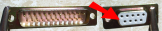
This picture shows a DB25 male plug and a DB9 female socket. If you look very carefully you will see that
both plugs and sockets have pin numbers embossed on the casing. This is almost impossible to read without
a magnifying glass and it is extremely important to accurately work out the pin numbers.
DTE/DCE... The Serial Version of Sex
Logic and simplicity would indicate that the signals in the circuits described above
would always be the same. Alas that is not the case.
Far back in the mists of ancient time, in the great and glorious days of the "glass teletype",
most serial cable was flat "ribbon" cable and the plugs were usually crimped onto the cable
without using any solder joints. But this meant that Pin 1 at one end, was always Pin 1 at
the other end.
Since an output at one end of a serial cable is an input to the device on
the other end, straight through connections would mean that an output was connected to an output at
the other end, and the same with inputs. This obviously wont work, since an output at one end
needs to be marched to an input at the other end.
Instead of matching inputs to outputs in the cable, it was decided to try and do the matching inside the devices.
In other words, one of the devices would have its pins do what is described, and the other device would have its
connections do the exact opposite. In this way, straight through ribbon cables could be used.
Devices which have their pins do what is described in the interface, are called DTE or Data Terminal Equipment.
Devices which do the opposite of what is described in the interface are called DCE or Data Communication Equipment.
The original concept was that a DTE device would always connect to a DCE device. But there was never any clear way to define
type of device was a DTE and what type of device was DCE. Some make sense. It makes sense to consider a modem as a DCE device
and a terminal as a DTE. But what about a printer? Data terminates there, and is not passed on, yet printers are almost
always connected to terminals. Almost immediately the differentiation between DTE and DCE became blurred. DTE devices were connected
to other DTE devices and the same with DCE devices.
In today's world, the terms DTE and DCE rarely make sense. Some devices are DTE and the pins on their interface do what is
described in the standard. Others are DCE, and their pins do the opposite. The manuals for the devices always describe the
signal names from the point of view of the DTE, but the documentation of DCE devices almost never indicates that the device
is DCE, and that the function of these pins is the opposite to what is described in the standard.
When designing a cable to connect serial devices, the first thing you need to do is determine whether the device is DTE or DCE.
Fortunately, this is very easy, and is described below. But any inference you draw from the plugs being male/female, the type of device
or the printed documentation, will very likely be wrong.
Back to top |
| |
|
The Nine Pins |
The following table shows the pins used in DB9 and DB25 connectors and their
function on DTE and DCE devices.
| Name |
DB25 Pin |
DB9 Pin |
DTE Function |
DCE Function |
| TXD |
2 |
3 |
Transmitted Data (Output) |
Received Data (Input) |
| RXD |
3 |
2 |
Received Data (Input) |
Transmitted Data (Output) |
| RTS |
4 |
7 |
Request To Send (Output) |
(Input) |
| CTS |
5 |
8 |
Clear To Send (Input) |
(Output) |
| DTR |
20 |
4 |
Data Terminal Ready(Output) |
(Input) |
| DSR |
6 |
6 |
Data Set Ready (Input) |
(Output) |
| SG |
7 |
5 |
Signal Ground (always connected) |
Signal Ground (always connected) |
| DCD |
8 |
1 |
Data Carrier Detect (Input) |
Data Carrier Detect (Output) |
| RI |
22 |
9 |
Ring Indicator (Input) |
Ring Indicator (Output) |
Note:- Some documentation describes Pin 1 on a DB25 connector as being Chassis or Frame Ground. This
may apply in other uses for DB25 connectors but does not apply for serial connections, and must not be used
otherwise hardware damage may occur.
Back to top |
| |
|
Common Cable Configurations |
While there are a lot of different ways that serial cables can be wired up
depending on the devices, there are a few methods that are used more often than others
and in many cases, you can follow these standard wiring diagrams if the type of connection
is one of the more common types.
Computer to Printer
Computers are almost always DTE devices using 9 pin D Connectors, and printers are
also almost always DTE devices, but frequently use 25 pin D connectors.
To fully implement a DTE to DTE serial cable using wither 9 pin or 25 pin connectors,
use the following diagram.
| DTE Computer |
DTE Printer |
| DB9 Pin# |
DB25 Pin# |
Signal Name |
Signal Name |
DB9 Pin# |
DB25 Pin# |
|
2 |
3 |
RXD Received Data |
TXD Transmitted Data |
3 |
2 |
|
3 |
2 |
TXD Received Data |
RXD Transmitted Data |
2 |
3 |
|
4 |
20 |
DTR Data Terminal Ready |
DSR Data Set Ready |
6 |
6 |
|
6 |
6 |
DSR Data Set Ready |
DTR Data Terminal Ready |
4 |
20 |
|
7 |
4 |
RTS Request to Send |
CTS Clear to Send |
8 |
5 |
|
8 |
5 |
CTS Clear to Send |
RTS Request to Send |
7 |
4 |
|
5 |
7 |
SG Signal Ground |
SG Signal Ground |
5 |
7 |
This cable fully implements a serial interface between two DTE devices, and uses
7 connections in the cable. This is because the Signals RI-Ring Indicator and DCD-Data Carrier Detect
which apply only to modems are not connected since modems are always DCE devices are these are both outputs
from the modem with no corresponding output from the DTE device.
This cable will work equally well for Hardware handshaking and for XON/XOFF handshaking.
If you will never use XON/XOFF (software) handshaking on this cable, then you can eliminate the first
connection shown in this table, since the printer will never transmit data to the computer.
If you will never use hardware handshaking DTR/DSR and/or RTS/CTS handshaking, and will always use
software handshaking XON/XOFF the you can use the following cable connections.
| DTE Computer |
DTE Printer |
| DB9 Pin# |
DB25 Pin# |
Signal Name |
Signal Name |
DB9 Pin# |
DB25 Pin# |
|
2 |
3 |
RXD Received Data |
TXD Transmitted Data |
3 |
2 |
|
3 |
2 |
TXD Received Data |
RXD Transmitted Data |
2 |
3 |
|
5 |
7 |
SG Signal Ground |
SG Signal Ground |
5 |
7 |
We do not recommend that you use software XON/XOFF software
handshaking or this cable configuration.
If you use this type3 of cable connection, many hardware devices still require that their inputs
be set correctly, or they will not work. You can fool the hardware by using the device outputs to
set the inputs.
This means that at each end, you would short out:-
- RTS and CTS
- DTR, DSR and often DCD
using a small piece of wire (or lump of solder) in the back of the connector.
This configuration matches up inputs to outputs for the two DTE devices. Notice that DCD
(Data Carrier Detect) and RI (Ring Indicator) are not connected. For a DTE device these are both
inputs, and there is no corresponding output pin on a DTE device.
Back to top |
| |
|
Figuring Out the Cable |
Back to the example of the printer shown earlier in this article. So, you have a device
and you think it uses a serial interface, but you don't know even the model or any of the details.
What do you do?
The first thing is to determine if the device is a DTE or a DCE serial device. Once you know this,
you can figure out most of the other connections.
The RS-232 standard, says that idling tranmitter pins are held with a voltage on the pin. In other
words, if the device is turned on but doing nothing, there will be a voltage on the pins it tranmists on
and if we can identify these pins we can compare the pin numbers with the cabling chart to determine if the
device is a DTE or DCE.
Tester
To make the cable, we will need to test if various signals are present on the devices at each end of the serial cable.
Fancy equipment is not required. Even cheap multimeters work poorly for this task, so we are going to make do with two LED's
and a 470 ohm resistor.
LED's or Light Emitting Diodes light up when voltage passes in one direction, but not the other direction.
By wiring up two different colored LED's in opposite directions we can detect a logic 0 and a logic 1 on any
of the serial lines. But in this case, we don't need to work out whether a signal is a logic 0 or a logic 1,
but only if there is a signal on a particular pin. So it does not matter whether we have different colored
LED's, just that they are connected in opposite directions so that one of these LED's will light up
if a signal is present.
The 470 ohm resistor is simply to protect the LED's because otherwise the LED's would go "pop" and stop working.
The voltages that appear on a serial interface are in the range of +25 Volts and -25 volts, and while this is
perfectly safe, and you will never damage the hardware even if you short out pins incorrectly, this voltage is too much for the LED's.
The connections should be made as follows.
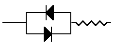
The two wires coming out of the LED are called the Anode and the Cathode, and those names indicate which way
the current flows. There is normally a bevel on the case of the LED to indicate which wire is which. In this case, we just need to
have them swapped around.
DTE or DCE
The first step to making a serial cable, is to determine whether a device is DTE or DCE.
The RS232 Serial standard states that idling transmitter pins are kept low. In other words, if a pin on the interface is a transmitting pin, and the device is turned
on, there should be a voltage asserted on that pin.
Connecting one end of the tester to the Signal Ground pin on the printer, we can then test by touching the other end of the tester on each of the other pins on
the printer plug, and see which of the pins lights up one of the LED's as follows:-
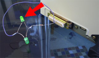
On this printer, the only pin which lights up is Pin 20. According to the table above, Pin 20 on a DB25
connector is DTR which is an output used by a DTE device to signal if it is online or not.
Normally on a DTE device, one would expect Pin 2 which is transmitted data to also have a voltage because this is the pin on which
a DTE device transmits data. This device, being a printer, is never going to transmit data however, so it is quite likely that
Pin 2 is not connected inside the printer.
Similarly this printer is never going to assert RTS (same reason... it is never going to send data), so it is not really surprising on an
older printer to see these signals unused.
What is more interesting, however, is that pressing the "Online" button on the front panel of the printer causes the other LED on Pin 20 of our tester
to light up as follows:-
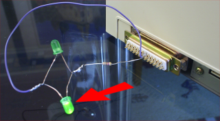
Excellent. Now we know that this printer is a DTE device which signals if it is online or offline using DTR, Pin 20.
Now to check the computer. Performing the same tests on the computer end which has a 9 pin male connector, shows that pins 3 and 4 both
turn on one of the LED's. Pin 3 on a DB9 is TXD (transmitted data by a DTE) and Pin 4 is DTR (Data Terminal Ready for a DTE). So the computer is
also a DTE.
The preferable way to make up a cable is to connect all the signals correctly, even if they are not required. That way, there is a good chance that the same
cable could be used for other connections as well. If one of the devices requires a signal that the other device does not supply, then we can do a slimy hack
to fool the interfaces into working. But we will only do this if absolutely necessary.
The way to match the signals between two DTE devices where one used a DB9 connector and the other used a DB25 connector would be as follows:-
| DB9 Pin# |
D9 Signal Name |
DB25 Pin# |
DB25 Signal Name |
|
2 |
RXD Received Data |
2 |
TXD Transmitted Data |
|
3 |
TXD Transmitted Data |
3 |
RXD Received Data |
|
4 |
DTR Data Terminal Ready |
6 |
DSR Data Set Ready |
|
5 |
SG Signal Ground |
7 |
SG Signal Ground |
|
6 |
DSR Data Set Ready |
20 |
DTR Terminal Ready |
|
7 |
RTS Request To Send |
5 |
CTS Clear to Send |
|
8 |
CTS Clear To Send |
4 |
RTS Request To Send |
This configuration matches up inputs to outputs for the two DTE devices. Notice that DCD
(Data Carrier Detect) and RI (Ring Indicator) are not connected. For a DTE device these are both
inputs, and there is no corresponding output pin on a DTE device.
Back to top |
| |
|
Tricking the Interface |
At this point, data should pass over the interface. Whether that data makes sense or not, is another matter.
It is necessary to have the serial ports configured to use the same Baud Rate, Data Bits, Stop Bits and parity.
On computers, these parameters are normally set in software. On devices such as printers, they are normally set
using dip switches. If you do not have documentation for the dip switch settings, it is usually better to try and use
the existing settings if you are using an old device, assuming that it did work previously, and knowing that there will be
ways of setting the dip switches so that the device does not work at all. If experimenting blind, then it is important
to keep accurate records of what you have tried, otherwise things can go badly wrong.
When changing dip switch settings, remember that the device only "reads" these settings
when it is powered on. You will need to turn off the device and then turn it back on for
the new settings to take effect.
In this example, everything worked perfectly with the cable made up. There are some cases where you may need to "spoof" one
of the devices that requires an input not required by the other device.
Say for example, you have a computer which requires that the DSR input be set in order to work, but the other device does not provide a DTR
output. In that case, nothing would happen over the interface. You could fool the computer into thinking that DSR
has been set by connecting the DTR and DSR pins on the computer end. The computer would then assert DTR, and when it went to read DSR, it
would be reading the output from its own DTR.
Another common hack is to connect the RTS, CTS and DCD pins inside the connector. This means that when a device asserts its RTS signal,
this signal is taken as input from the other device telling it that the other device can receive data and also has DCD from a modem asserted.
Do these trick only if it is absolutely necessary. Many older cables routinely had pins 4 and 5 joined inside the plugs as well as pins
6, 8, and 20. This is not good practice, and should be avoided if possible.
Back to top |
| |
Copyright © 2004-2006, himatix.com
|
|